The Secret of Stunning Microphone Woven Wired Mesh Grid Design in CAD With 6 main steps
Have you ever noticed the detailed mesh grid on a microphone and wondered how it’s created? It’s not just a repeating pattern—it’s a result of smart engineering and advanced CAD skills. Making a realistic, interlocking mesh that fits smoothly over a sphere might seem difficult, but with the right steps in Onshape, it’s easier than you think and leads to impressive results.
This guide will walk you through the process of designing a complex, curved woven wire mesh—like the kind you see on professional microphones. Instead of a flat texture, we’ll show you how to replicate the smooth, natural curves found in real products. You’ll learn each step in a clear, easy-to-follow way, focusing on surface modeling and 3D splines.
The secret to this complex geometry lies in a sophisticated interplay of surface splitting, 3D splines, and a specialized sweep feature. This process allows us to generate intricate, interlocking wave curves that precisely map onto a curved surface, which are then transformed into robust wires. It might sound complex, but by the end of this tutorial, you’ll have the knowledge to execute this masterful design.
The Foundation: Building The Base Surface Shape
In this guide, we will use the sphere surface as an example. That’s the base surface we are working on. Do not worry, all steps apart from the base shape example are valid for the other shapes that we most often see on a microphone head.
- Design half of the sphere: Begin by selecting a Plane (front plane or right plane is OK) in Onshape. This is your primary sketching environment. Think of it as looking straight at the microphone head you intend to design.
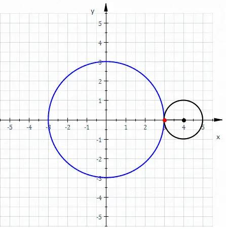
- Sketching the Profile: On this plane, draw 2 lines and turn them into construction lines. Then use 3-Point-Arc and draw an arc from the End of the 2 lines you drew. Set the dimension of the line. In my case, I chose 40mm as a radius. But most of the microphone Head is about 45mm in Diameter.

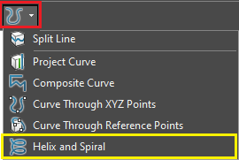
- The Revolve Feature: Once your sketch is complete, use Revolve/Surface. Select your sketched profile and an axis (typically the central axis of your sketch). Onshape will then spin your 2D profile around that axis, generating a perfectly smooth, 3D spherical surface. This surface is the very foundation upon which our intricate mesh will be built.

Crucial step: Patterning the Mesh Guides
Now that we have our spherical base, the next step is to define the initial guides that will help us segment this surface. These guides are crucial for establishing the underlying structure of our woven pattern.
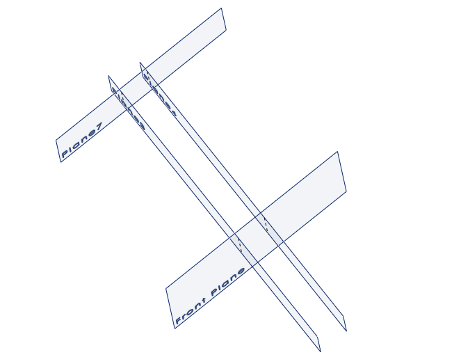
- Guide sketch: Switch your view back to the Front Plane (or Right Plane). This is where we’ll sketch the lines that will dictate the first stage of our mesh pattern.
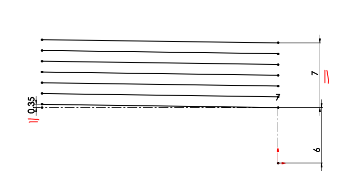
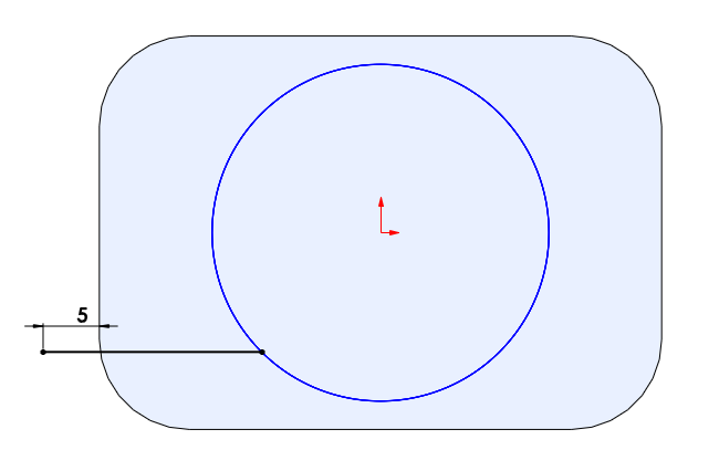
- Drawing the Radii: Draw a line that passes through the origin and passes through the Sphere’s surface. Turn that line into a construction line. Add a Dimension between the end of the line and the origin as an offset dimension. You can experiment with that Dimension. In my case, I chose 30mm.
- Create Angular lines Patterns: Create lines that we need for the guides. Use the bottom End of the 1st line we drew as the angular origin. Drew lines that fit the base surface. In this Example, I chose 4 lines. Then set the angle. So the angle between the construction line and the 2nd line, in my case, is 7.5 degrees. And between the 2nd line and the 3rd line is 15 degrees. And the rest will be this 15 degrees.

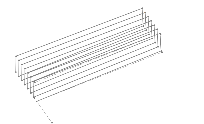
- Extruding the Guides: After that, Extrude/surface those lines. Make sure that the Extrude Distance you set covers your base surface. Do not forget to check the “symmetry” option when extruding.
Custom Checker Pattern Guide
This is where our flat 2D guides begin to transform into dynamic 3D elements that conform to our spherical shape. Surface splitting is a powerful tool that allows us to carve our base surface using other geometric entities.
- Circular Pattern: Pattern the Extruded lines we created in the previous step. Use a Circular pattern, and pattern bodies 4 times.

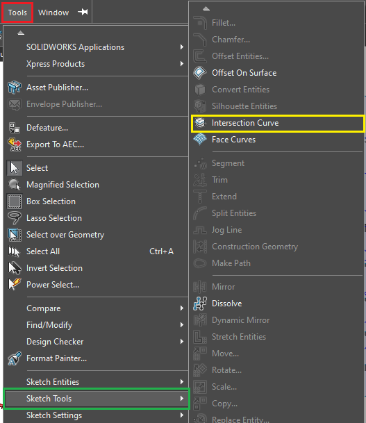
- Create a Custom Checker Pattern Guide: After patterning, click on the Split commands and choose the Face tab. Choose the sphere as the Face to split with, and choose the other surfaces as the entities to split with. Uncheck “the keep tools” because we do not need the tool anymore.

Refining the Canvas: Preparation and Offset
Before we can start drawing our intricate 3D wave curves, we need to refine our split surface and create the necessary space for the “weaving” effect. This involves a bit of strategic cleanup and duplication.
- Strategic Face Deletion: This step might seem counterintuitive, but it’s essential for simplifying the design process. You’ll need to delete faces from your newly split spherical surface. This focus allows for clearer visualization as you construct the intricate spline paths. Delete faces like checkers. Keep the center faces, but delete the rows next to them. It will help you with the pattern in the last step. And only delete faces on the half of the sphere.
- Offsetting the Surface: Now, select the entire remaining surface (not just a single face) and use the Offset feature. This creates a parallel duplicate of your surface, positioned at a specific distance from the original.

The Heart of the Mesh: Crafting Interlocking Wave Curves
This is arguably the most artistic and critical step in the entire process. Here, we’ll use 3D splines to draw the paths that our wires will follow, creating that characteristic woven look. The key is careful point placement and alternating between your two offset surfaces.
- Initiating the First Wave: Activate the 3D Spline tool. This allows you to draw curves directly in 3D space, unbound by a single sketch plane.
- Alternating Points – The Weaving Secret: The magic happens by strategically placing the spline points. You can check here for more explanation
- For your very first point, start on the offsetted surface.
- For the second point, switch and place it on the original surface.
- Continue this pattern: the third point goes back to the offsetted surface, the fourth to the original, and so on. This continuous alternation between the two surfaces is what generates the natural “over and under” effect of a woven mesh.
- Pro-Tip: Pay close attention to the visual cues provided by your split surfaces. The grid lines created by the initial splitting will serve as excellent guides for where to place your spline points, ensuring a uniform and aesthetically pleasing pattern.
- The Next Wave – Opposite Start: When you begin drawing your next wave curve, it’s crucial to start on the opposite surface from where your previous curve began. If your first curve started on the offset surface, your second curve must begin on the original surface. This ensures that the two curves interlock correctly, creating that authentic woven appearance.
- Repeating the Pattern: Continue creating all the necessary wave curves for one segment of your mesh. Remember to alternate the starting surface for each new line to maintain the interlocking pattern. This meticulous process builds the core weaving structure.

Bringing it to Life: Wires and Final Pattern
With all your intricate 3D spline curves in place, the final steps involve transforming these abstract lines into tangible wires and then replicating them across the entire sphere to form the complete mesh.
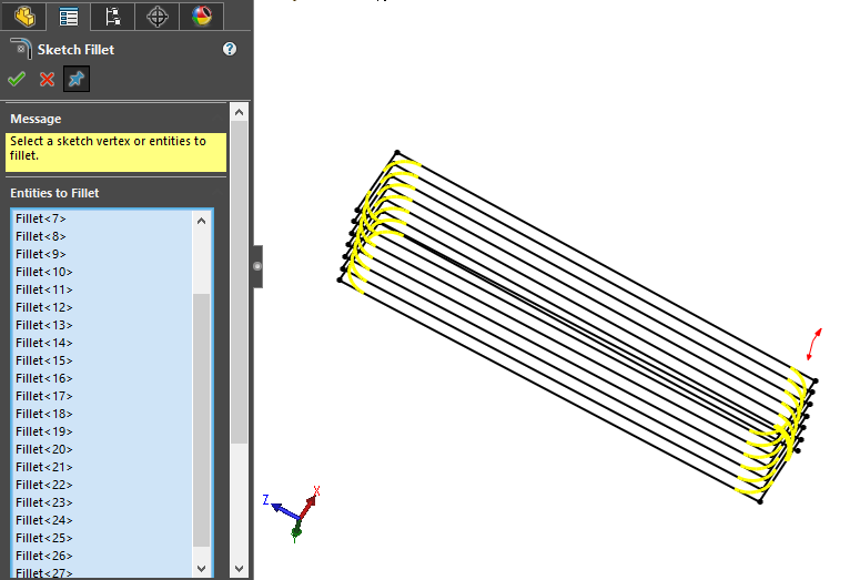
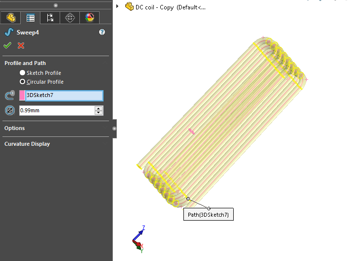
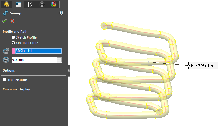
- The “Circle Sweep” Feature Script: This is where Onshape’s flexibility truly shines. Instead of using the standard, more manual Sweep feature, leverage a custom Feature Script. We recommend searching the Onshape App Store or community forums for a tool like “Circle Sweep”. This script is a game-changer because it allows you to quickly generate a uniform, round 3D wire body along your selected spline curves with minimal effort. This significantly speeds up the process compared to sketching a circular profile and sweeping it manually for each curve.
- Applying to All Curves: Apply the Circle Sweep feature to every single one of the wave curves you meticulously created. Watch as your delicate 3D splines instantly transform into robust, metallic wires, forming the initial woven segment of your microphone mesh.
- The Grand Finale: Circular Pattern: With your primary wire segment complete, the very last step is to perform a final Circular Pattern on all the wire bodies you’ve just created. Select all the individual wire components, choose your central axis, and define the number of instances needed to fully encircle your spherical base. Onshape will then replicate your woven segment, completing the full, stunning microphone mesh grid.

Beyond the Mesh: Your Design Journey Continues
And there you have it! A comprehensive breakdown of how to design a highly detailed, realistic woven wire mesh on a non-planar surface using advanced Onshape techniques. This method transcends basic patterning, allowing you to create designs that truly mimic the organic, complex nature of real-world objects like microphone grids.
This Technics can be used with other CAD software such as Solidworks, Fusion360
What complex geometric challenge will you tackle next?
If you need a clear explanation video, Watch here 👇
The Secret of Stunning Microphone Woven Wired Mesh Grid Design in CAD With 6 main steps Read More »


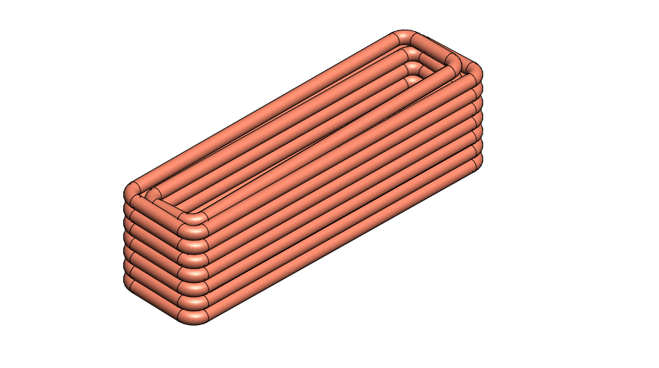
 Your rectangle spring is done.